
No, not the pseudoscience stuff, I am talking about Direct Memory Access. More specifically in the context of IBM PC and compatibles, which use the Intel 8237A DMA controller.
For some reason, I had never used the 8237A before. I suppose that’s because the DMA controller has very limited use. In theory it can perform memory-to-memory operations, but only between channels 0 and 1, and IBM hardwired channel 0 to perform memory refresh on the PC/XT, so using channel 0 for anything else has its consequences. Aside from that, the 8237A is a 16-bit DMA controller shoehorned into a 20-bit address space. So the DMA controller can only address 64k of memory. IBM added external ‘page registers’ for each channel, so you can store the high 4 bits of the 20-bit address there, and this will be combined with the low 16-bit address from the DMA controller on the bus. This means there are only 16 pages of 64k, aligned to 64k boundaries (so you have to be careful when allocating a buffer for DMA, you need to align it properly so you do not cross a page boundary. Beyond 64k, the addressing just wraps around). However, since channel 0 was reserved for memory refresh on the PC/XT, they did not add a page register for it. This means that you can only do memory-to-memory transfers within the same 64k page of channel 1, which is not very useful in general.
On the AT however, they added separate memory refresh circuitry, so channel 0 now became available for general use. They also introduced a new page register for it (as well as a second DMA controller for 16-bit DMA transfers, as I also mentioned in this earlier article). So on an AT it may actually work. There is another catch, however: The 8237A was never designed to run at speeds beyond 5 MHz. So where the 8237A runs at the full 4.77 MHz on a regular PC/XT, it runs at half the clockspeed on an AT (either 3 or 4 MHz, depending on whether you have a 6 or 8 MHz model). So DMA transfers are actually slower on an AT than on a PC/XT. At the same time the CPU is considerably faster. Which means that most of the time, you’re better off using the CPU for memory-to-memory transfers.
Therefore, DMA is mostly used for transferring data to/from I/O devices. Its main uses are for floppy and harddrive transfers, and audio devices. Being primarily a graphics programmer, I never had any need for that. I needed memory-to-memory transfers. You generally don’t want to implement your own floppy and harddrive handling on PC, because of the variety of hardware out there. It is better to rely on BIOS or DOS routines, because they abstract the hardware differences away.
It begins
But in the past weeks/months I have finally been doing some serious audio programming, so I eventually arrived at a need for DMA: the Sound Blaster. In order to play high-quality digital audio (up to 23 kHz 8-bit mono) on the Sound Blaster, you have to set up a DMA transfer. The DSP (‘Digital Sound Processor’ in this context, not Signal) on the SB will read the samples from memory via DMA, using an internal timer to maintain a fixed sampling rate. So playing a sample is like a ‘fire-and-forget’ operation: you set up the DMA controller and DSP to transfer N bytes, and the sample will play without any further intervention from the CPU.
This is a big step up from the sample playing we have been doing so far, with the PC Speaker, Covox or SN76489 (‘Tandy/PCjr’ audio). Namely, all these devices required the CPU to output individual samples to the device. The CPU was responsible for accurate timing. This requires either cycle-counted loops or high-frequency timer interrupts. Using DMA is more convenient than a cycle-counted loop, and far more efficient than having to handle an interrupt for every single sample. You can now play back 23 kHz mono 8-bit audio at little more than the cost of the bandwidth on the data bus (which is about 23 kb/s in this case: you transfer 1 byte for each sample), so you still have plenty of processing time left to do other stuff. The DMA controller will just periodically signal a HOLD to the CPU. Once the CPU acknowledges this with a HLDA signal, the DMA controller has now taken over the bus from the CPU (‘stealing cycles’), and can put a word from memory onto the bus for the I/O device to consume. The CPU won’t be able to use the bus until the DMA transfer is complete (this can either be a single byte transfer or a block transfer).
It’s never that easy
If it sounds too good to be true, it usually is, right? Well, in a way, yes. At least, it is for my chosen target: the original Sound Blaster 1.0. It makes sense that when you target the original IBM PC 5150/5160, that you also target the original Sound Blaster, right? Well, as usual, this opened up a can of worms. The keyword here is ‘seamless playback’. As stated above, the DMA controller can only transfer up to 64k at a time. At 22 kHz that is about 3 seconds of audio. How do you handle longer samples?
After the DMA transfer is complete, the DSP will issue an interrupt. For longer samples you are expected to send the next buffer of up to 64k immediately. And that is where the trouble is. No matter what you try, you cannot start the next buffer quickly enough. The DSP has a ‘busy’ flag, and you need to wait for the flag to clear before you send each command byte. I have measured that on my 8088 at 4.77 MHz, it takes 316 cycles to send the 3 bytes required for a new buffer command (the 0x14 command to play a DMA buffer, then the low byte and high byte of the number of samples to play). At 4.77 MHz, a single sample at 22050 Hz lasts about 216 CPU cycles. So you just cannot start a new transfer quickly enough. There is always a small ‘glitch’. A faster CPU doesn’t help: it’s the DSP that is the bottleneck. And you have to wait for the busy-flag to clear, because if you don’t, it will not process the command properly.
Nagging the DSP
Some early software tried to be creative (no pun intended) with the Sound Blaster, and implemented unusual ways to output sound. One example is Crystal Dream, which uses a method that is described by Jon Campbell of DOSBox-X as ‘Nagging the DSP’. Crystal Dream does not bother with the interrupt at all. Apparently they found out that you can just send a new 0x14 command, regardless of whether you received and acknowledged the interrupt or not. In fact, you can even send it while the buffer is still playing. You will simply ‘restart’ the DSP with a new buffer.
Now, it would be great if this resulted in seamless output, but experimentation on real hardware revealed that this is not the case (I have made a small test program which people can run on their hardware here).. Apparently the output stops as soon as you send the 0x14 command, and it doesn’t start again until you’ve sent all 3 bytes, which still takes those 316 cycles, so you effectively get the exact same glitching as you would with a proper interrupt handler.
State of confusion
So what is the solution here? Well, I’m afraid there is no software-solution. It is just a design-flaw in the DSP. This only affects DSP v1.xx. Later Sound Blaster 1.x cards were sold with DSP v2.00, and Creative also offered these DSPs as upgrades to existing users, as the rest of the hardware was not changed. See this old Microsoft page for more information. The early Sound Blasters had a ‘click’ in digital output that they could not get rid of:
If a board with the versions 1.x DSP is installed and Multimedia Windows is running in enhanced mode, a periodic click is audible when playing a wave file. This is caused by interrupt latency, meaning that interrupts are not serviced immediately. This causes the Sound Blaster to click because the versions 1.x DSP produce an interrupt when the current DMA buffer is exhausted. The click is the time it takes for the interrupt to be serviced by the Sound Blaster driver (which is delayed by the 386 enhanced mode of Windows).
The click is still present in standard mode, although it is much less pronounced because the interrupt latency is less. The click is more pronounced for pure tones.
The version 2.0 DSP solves this problem by using the auto- initialize mode of the DMA controller (the 8237). In this mode, the DMA controller automatically reloads the start address and count registers with the original values. In this way, the Sound Blaster driver can allocate a 4K DMA buffer; using the lower 2K as the “ping” buffer and the upper 2K as the “pong” buffer.
While the DMA controller is processing the contents of the ping buffer, the driver can update the pong; and vice versa. Therefore, when the DMA controller auto-initializes, it will already have valid data available. This removes the click from the output sound.
What is confusing here, is the nomenclature that the Sound Blaster Hardware Programming Guide uses:
Single-cycle DMA mode
They refer to the ‘legacy’ DSP v1.xx output mode as ‘single-cycle DMA mode’. Which is true, in a sense: You program the DMA controller for a ‘single transfer mode’ read. A single-cycle transfer means that the DMA controller will transfer one byte at a time, when a device does a DMA request. After that, the bus is released to the CPU again. Which makes sense for a DAC, since it wants to play the sample data at a specific rate, such as 22 kHz. For the next byte, the DSP will initiate a new DMA request by asserting the DREQ line again. This opposed to a ‘block transfer’ where the DMA controller will fetch the next byte immediately after each transfer, so a device can consume data as quickly as possible, without having to explicitly signal a DREQ for each byte.
Auto-Initialize DMA mode
The ‘new’ DSP 2.00+ output mode is called ‘auto-initialize DMA mode’. In this mode, the DSP will automatically restart the transfer at every interrupt. This gives you seamless playback, because it no longer has to process a command from the CPU.
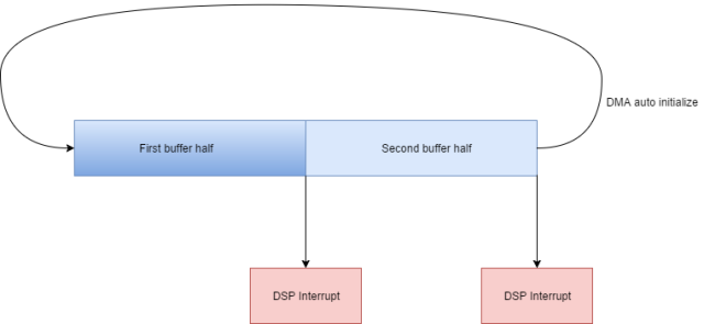
The confusion here is that the DMA controller also has an ‘autoinitialize mode’. This mode will automatically reload the address and count registers after a transfer is complete. So the DMA controller is immediately reinitialized to perform the same transfer again. Basically the same as what the DSP is doing in ‘auto-initialize DMA mode’. You normally want to use both the DMA controller and DSP in their respective auto-init modes. Double-buffering can then be done by setting up the DMA controller with a transfer count that is twice as large as the block size you set to the DSP. As a result, the DSP will give you an interrupt when it is halfway the DMA buffer, and another one when it is at the end. That way you can re-fill the half of the buffer that has just finished playing at each interrupt, without any need to perform extra synchronization anywhere. The DMA controller will automatically go back to the start of the buffer, and the DSP also restarts its transfer, and will keep requesting data, so effectively you have created a ringbuffer:
However, for the DMA controller, this is not a separate kind of transfer, but rather a mode that you can enable for any of the transfer types (single transfer, block transfer or demand). So you are still performing a ‘single transfer’ on the DMA controller (one byte for every DREQ), just with auto-init enabled.
You can also use this auto-init mode when using the legacy single-cycle mode of the DSP, because the DSP doesn’t know or care who or what programs the DMA, or what its address and count are. It simply requests the DMA controller to transfer a byte, nothing more. So by using auto-init on the DMA controller you can at least remove the overhead of having to reprogram DMA at every interrupt in single-cycle mode. You only have to send a new command to the DSP, to minimize the glitch.
Various sources seem to confuse the two types of auto-init, thinking they are the same thing and/or that they can only be used together. Not at all. In theory you can use the single-cycle mode for double-buffering in the same way as they recommend for auto-init mode: Set the DMA transfer count to twice the block size for the DSP, so you get two interrupts per buffer.
And then there is GoldPlay… It also gets creative with the Sound Blaster. Namely, it sets up a DMA transfer of only a single byte, with the DMA controller in auto-init mode. So if you start a DSP transfer, it would just loop over the same sample endlessly, right? Well no, because GoldPlay sets up a timer interrupt handler that updates that sample at the replay frequency.
That is silly and smart at the same time, depending on how you look at it. Silly, because you basically give up the advantage of ‘Fire-and-forget’ DMA transfers, and you’re back to outputting CPU-timed samples like on a PC speaker or Covox. But smart, for exactly that reason: you can ‘retrofit’ Sound Blaster support quite easily to a system that is already capable of playing sound on a PC speaker/Covox. That is probably the reason why they did it this way. Crystal Dream also uses this approach by the way.
There is a slight flaw there, however. And that is that the DSP does not run in sync with the CPU. The DSP has its own crystal on the card. What this means is that you probably will eventually either miss a sample completely, or the same sample gets output twice, when the timer and DSP go out of sync too far. But since these early SB cards already have glitches by design, one extra glitch every now and then is no big deal either, right?
The best of both worlds
Well, not for me. I see two requirements here:
- We want as few glitches as possible.
- We want low latency when outputting audio.
For the DSP auto-init mode, it would be simple: You just set your DMA buffer to a small size to have low latency, and handle the interrupts from the DSP to update the buffers. You don’t have to worry about glitches.
For single-cycle mode, the smaller your buffers, the more glitches you get. So the two requirements seem mutually exclusive.
But they might not be. As GoldPlay and Crystal Dream show, you don’t have to match the buffer size of the DMA with the DSP at all. So you can set the DSP to the maximum length of 64k samples, to get the least amount of glitches possible.
Setting the DMA buffer to just 1 sample would not be my choice, however. That defeats the purpose of having a Sound Blaster. I would rather set up a timer interrupt to fire once every N samples, so the timer interrupt would be a replacement for the ‘real’ DSP interrupt you’d get in auto-init mode. If you choose your DSP length to be a multiple of the N samples you choose for your DMA buffer, you can reset the timer everytime the DSP interrupt occurs, so that you re-sync the two. Be careful of the race condition that theoretically the DSP and timer should fire at the same time at the end of the buffer. Since they run on different clock generators, you never know which will fire first.
One way to get around that would be to implement some kind of flag to see if the timer interrupt had already fired, eg a counter would do. You know how many interrupts to expect, so you could just check the counter in the timer interrupt, and not perform the update when the counter exceeds the expected value. Or, you could turn it around: just increment the counter in the timer interrupt. Then when the DSP interrupt fires, you check the counter, and if you see the timer had not fired yet, you can perform the last update from the DSP handler instead. That removes the branching from the timer interrupt.
Another way could be to take the ‘latched timer’ approach, as I also discussed in a previous article. You define a list of PIT count values, and update the count at every interrupt, walking down the list. You’d just set the last count in the list to a value of 0 (interpreted as 65536 ticks), so you’re sure it never fires before the DSP does.
Once you have that up and running, you’ll have the same low-latency and low CPU load as with DSP v2.00+, and your glitches will be reduced to the minimum possible. Of course I would only recommend the above method as a fallback for DSP v1.xx. On other hardware, you should just use auto-init, which is 100% glitch-free.
Update 17-04-2017: I read the following on the OSdev page on ISA DMA:
Some expansion cards do not support auto-init DMA such as Sound Blaster 1.x. These devices will crash if used with auto-init DMA. Sound Blaster 2.0 and later do support auto-init DMA.
This is what I thought was some of the ‘confusion’ I described above regarding auto-init mode on the SB DSP vs the DMA controller. But I did not want to include anything on it until I was absolutely sure. But NewRisingSun has verified this on a real Sound Blaster with DSP v1.05 over at the Vogons forum. He ran my test program, which uses auto-init DMA, while performing single-cycle buffer playback on the DSP (the only type the v1.xx DSP supports). And it plays just fine, like the DSP v2.xx and v3.xx we’ve tested with. So no crashing. The quote from OSDev is probably confusing DMA auto-init mode with the fact that Sound Blaster 1.x with DSP v1.xx do not have the auto-init DSP command (which won’t make them crash either, they just don’t know the command, so they won’t play). In short, that information is wrong. DMA auto-init transfers work fine on any Sound Blaster, and are recommended, because they save you the CPU-overhead of reprogramming the DMA controller after every transfer. You only have to restart the DSP.

May be worth mentioning that the DSP was in fact a processor… an Intel 8051 or something like that. I wonder if anyone managed to get a ROM dump out of a 1.x or 2.0 DSP yet?
If I understood you correctly, it was absolutely impossible to do glitch-free DMA playback on the 1.x DSPs because you had to write a new DSP command to continue playing, and while the command was being written, the playback always stopped. That’s pretty amazingly shoddy design, even for a 1.0 product.
In the old days, DMA was absolutely essential for floppy transfers. Starting with the PC/AT it was almost never used for any hard disks, and very rarely for network cards or other devices. At least the better SCSI controllers used bus-mastering DMA where they did program the 8237A but didn’t actually use it for pushing data. It was basically floppies and sound cards.
In PCI days, DMA caused major headaches for sound card manufacturers because Sound Blaster compatibility absolutely needs DMA, but PCI is really not friendly with the 8237A-style DMA. So various schemes were invented, like Distributed DMA, PC/PCI, and so on. It was an especially big problem for laptops where an ISA or ISA-like DMA device might be behind a bridge or on a PC Card.
It’s hard to blame Creative for using 8237A DMA, it made perfect sense for a device which didn’t need a lot of bandwidth but where low latency was critical. But thank goodness that kind of DMA is gone.
Yes, seems like they were merely thinking of playing single triggered samples of 64kb length max. Good enough for sound effects.
Given that you could upgrade the DSP, it was clearly just a software limitation on the DSP side.
Michal, you wrote about dumped soundblaster DSP firmware yourself in 2015 ;). apparently its in the MESS 0.151 ROM collection.
SB16 DSP yes. SB 1.x firmware I haven’t seen. I could not find anything in the MESS ROM collection but I could have very easily overlooked it.
I recently had an occasion to revisit this topic and found the Creative documentation to be maddeningly confusing, just like the blog post says. The way they use the term “auto-init” to kind of mean both a SB DSP command and an 8237A option is stupid. They definitely aren’t the same, and certainly can be used independently of each other. Similarly “single-cycle” is really close to the 8237A “single transfer mode”, but they are different things. The term “transfer mode” too has one meaning for the SB DSP and another for the DMA controller.
It reads like the docs were written by people who didn’t really know how the 8237A works, but knew that if they program the 8237A “like this”, it does what they need. Other programmers did things differently, maybe because they knew more or maybe because they knew even less.
Not long ago I also looked at the 3Com 3C500/3C501 EtherLink, which can use DMA. The 3Com documentation is a lot less confusing than Creative’s, because it says essentially nothing whatsoever about how to use DMA with the card, so there’s nothing potentially misleading.
Pingback: Audio Frequency Data Acquisition | OS/2 Museum
Pingback: What makes the PCjr cool, and what makes it uncool? | Scali's OpenBlog™
Pingback: Древности: чем хуже, тем лучше или особенности Sound Blaster Pro 2 – CHEPA website
Pingback: DOSBox Shaders Comparison For Modern DOS Retro Gaming - Krystof.IO
Pingback: Do 8-bit DACs result in 8-bit audio quality? | Scali's OpenBlog™
Pingback: Video playback on low-end MS-DOS machines | Scali's OpenBlog™